
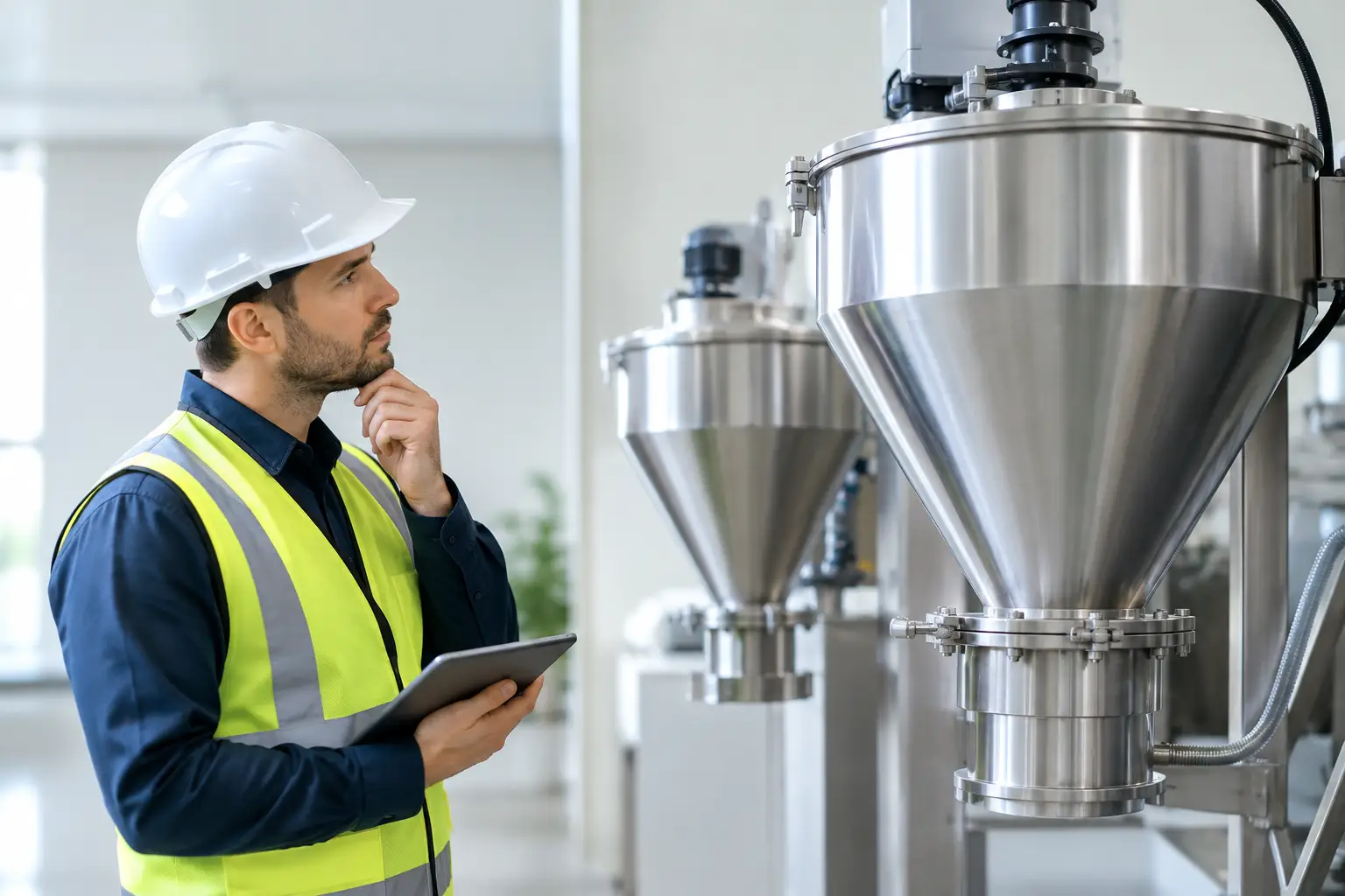
A vacuum hopper that is too small can leave a production line starved of material. One that is unnecessarily large can increase capital cost, take up valuable floor space and make cleaning or changeovers slower. To select vacuum hopper capacity correctly, start with the process demand rather than choosing a vessel size from a catalogue.
For pneumatic conveying systems, the hopper is more than a collection point. It is the receiver that separates conveyed material from the air stream, stores enough product to cover the discharge cycle, and feeds the next stage of the process reliably. Its capacity must suit the material, the conveying distance, the production rate and the way the line operates.
What Vacuum Hopper Capacity Controls
Hopper capacity affects the stability of the whole conveying system. If the receiver reaches its maximum fill level before the transfer cycle is complete, the system can lose throughput or block the line. If it empties before the next conveying cycle has delivered enough material, downstream equipment may run inconsistently or stop altogether.
The right size also gives the vacuum producer, filters and discharge valve sufficient time to do their jobs. A vacuum hopper is typically filled under vacuum, isolated, vented and then discharged. In continuous processes, these stages repeat constantly. The usable storage volume has to bridge the time between deliveries while allowing for the material left in the hopper at high and low level set points.
This is why nominal vessel volume alone is not a reliable selection criterion. A 500-litre hopper does not necessarily provide 500 litres of usable material storage. The operating level range, material flow behaviour and discharge arrangement all reduce the practical capacity available to the process.
How to Select Vacuum Hopper Capacity From Process Demand
The first figure to establish is the required material flow rate. This may be expressed in kilograms per hour, tonnes per shift or batches per day. Use the maximum credible production demand, not only the average rate. A system designed solely around average consumption may perform well during normal running but fail when the line accelerates, multiple users call for material or a surge in demand occurs.
Next, establish how long the hopper must support the process between filling cycles. This includes the vacuum conveying period, filter cleaning interval where applicable, valve operation, venting and discharge time. It should also account for the expected variation in material pickup from the source container, bulk bag station, silo or machine collection point.
A useful starting calculation is:
Gross hopper volume = required material per cycle ÷ bulk density ÷ usable fill fraction
For example, a process consuming 600 kg of material per hour requires 100 kg during a ten-minute operating cycle. If the material has a bulk density of 600 kg/m³, that material occupies approximately 0.167 m³, or 167 litres. If only 70% of the hopper volume is treated as usable working capacity, the receiver should provide at least 238 litres before any allowance for future growth or abnormal operating conditions.
The usable fill fraction is a practical engineering allowance. It recognises that a hopper should not normally fill to the filter housing or discharge down to an unreliable trickle. Depending on the material and receiver design, a working fill range of around 60% to 80% may be appropriate. Free-flowing pellets can often work closer to the upper end; difficult powders may need more space and a more conservative operating range.
Size for Peak Rate, Not Just Average Rate
Peak demand matters particularly where a single vacuum system serves more than one machine. A centralised system may experience overlapping requests from several process stations, even when each machine’s average use is modest. The hopper capacity must therefore be assessed alongside vacuum pump output, pipework sizing and the selected conveying sequence.
A larger receiver can provide useful buffering, but it cannot correct a system that does not convey material quickly enough. If the vacuum unit, pipeline or pickup arrangement cannot achieve the required transfer rate, increasing hopper volume only delays the point at which the process runs short.
Allow for Real Cycle Time
Theoretical cycle times are rarely achieved on every cycle. Material may take longer to lift from a low source level, filters can require cleaning, and discharge valves may need longer to clear sticky or slow-moving product. Where uninterrupted feed is critical, assess the longest realistic cycle rather than the best-case figure.
For applications with high consumption and little tolerance for interruption, twin receivers or alternating vacuum hoppers may be more appropriate than a single oversized vessel. One hopper can fill while the other discharges, providing a more consistent feed to the process. The correct arrangement depends on the required duty, product characteristics and available installation space.
Material Properties Change the Capacity Requirement
Two materials with the same bulk density can behave very differently in a vacuum hopper. Granules, metal shot and plastic regrind tend to settle predictably. Fine powders, fibres, flakes, moist materials and irregular chips can retain air, bridge across the outlet or compact during conveying.
Aerated powders are a common example. Material entering the hopper may occupy more volume immediately after transfer than it does after settling. If the receiver is sized only from settled bulk density, it may reach the high-level point earlier than expected. A larger freeboard allowance, controlled fill rate or a hopper designed to aid de-aeration may be required.
Flowability at discharge is equally relevant. A hopper needs sufficient cone angle, suitable outlet diameter and, where necessary, flow aids such as vibration or fluidisation. Adding volume above a poorly designed outlet does not improve throughput. It may simply leave more material held up in the vessel, increasing cleaning time and reducing the usable capacity.
For recovered process waste, the material mix may also change. Swarf containing cutting fluid, fine grinding dust, powder residues or mixed packaging waste should be evaluated as it appears in practice, not as a clean sample. Wet, cohesive or variable materials usually demand greater operating allowance than uniform dry granules.
Match the Hopper to the Discharge Method
The discharge method determines how much of the hopper is genuinely available to the process. A flap valve, rotary valve, slide gate or screw feeder all have different characteristics. Their opening time, sealing performance and ability to handle abrasive or awkward material must be considered with the receiver volume.
A vacuum hopper that discharges by gravity needs adequate headroom below the outlet and a material that will flow consistently. If the hopper feeds a screw conveyor, mixer or dosing system, the downstream equipment may impose its own maximum feed rate. In that case, the hopper should be selected as a buffer between two different rates: the intermittent conveying rate and the controlled process feed rate.
Level controls deserve equal attention. High-level protection prevents material from reaching filters and entering the vacuum line. Low-level sensing should trigger replenishment early enough to maintain supply. The distance between these two set points is the effective working capacity, and it may be significantly less than the vessel’s total rated volume.
Do Not Treat Safety Features as Optional Extras
Where combustible dust is present, hopper capacity and configuration must be considered within the wider hazardous-area assessment. A vessel of the right size still requires suitable filtration, grounding, pressure relief or isolation measures and an appropriately specified ATEX solution where the risk assessment calls for it.
Material temperature is another consideration. Hot ash, metal fines or process residues can affect filter selection, seals and safe operating limits. Abrasive products may require wear-resistant construction or replaceable components, while food, pharmaceutical or high-purity applications may require finishes that support thorough clean-down and prevent cross-contamination.
Capacity selection should never be separated from these requirements. The vessel, filter, vacuum source, controls and discharge equipment work as one engineered system.
Common Sizing Mistakes to Avoid
The most frequent mistake is selecting a hopper by litres alone. Capacity must be tied to mass flow, bulk density and the usable level range. Another is overlooking changes in the material itself, such as a new grade of powder, higher moisture content or a growing proportion of fines.
It is also easy to ignore future demand. If a line is expected to add shifts, increase output or supply an additional machine, allowing sensible capacity headroom at the design stage is usually more cost-effective than replacing a receiver later. That said, excessive oversizing is not automatically beneficial. It can make batch changeovers longer, increase retained material and complicate cleaning.
Finally, avoid specifying the receiver without examining the installation. Ceiling height, access for filter maintenance, fork-lift routes, source location and the length of vacuum pipework can all influence the practical hopper design. A tailored layout often delivers better operating performance than a nominally larger standard vessel.
Forvac Industrial assesses vacuum hopper capacity as part of the complete conveying duty, from material pickup through to controlled discharge. The most useful information to gather before selecting equipment is the material type, bulk density, maximum hourly demand, desired run time between fills, conveying distance and any ATEX or hygiene requirements. With those details established, capacity becomes a controlled engineering decision rather than an educated guess.
